The 3D view is built from what goes to the fab.

Not a picture drawn beside the board — the same copper, pads, drills and silkscreen geometry that comes back out as Gerber, drill, STEP and VRML. If the 3D view is wrong, the fab files are wrong the same way, which is the only way a 3D preview is worth trusting.

macOS, Windows and Linux · no account. Every platform.

A populated two-layer board in Rivet PCB's 3D viewer: electrolytic capacitors, a barrel jack, a QFN, pin headers and a ground pour.
Built from the same geometry the fab gets — not a picture drawn beside it.

The details that matter

01

The things a board comes back wrong for.

A fab drawing that looks right at a glance can still be wrong in the geometry that actually matters — a pad connected solid to a pour instead of through a thermal relief, or a slot drawn as a round hole. The viewer draws these because the export files carry them.

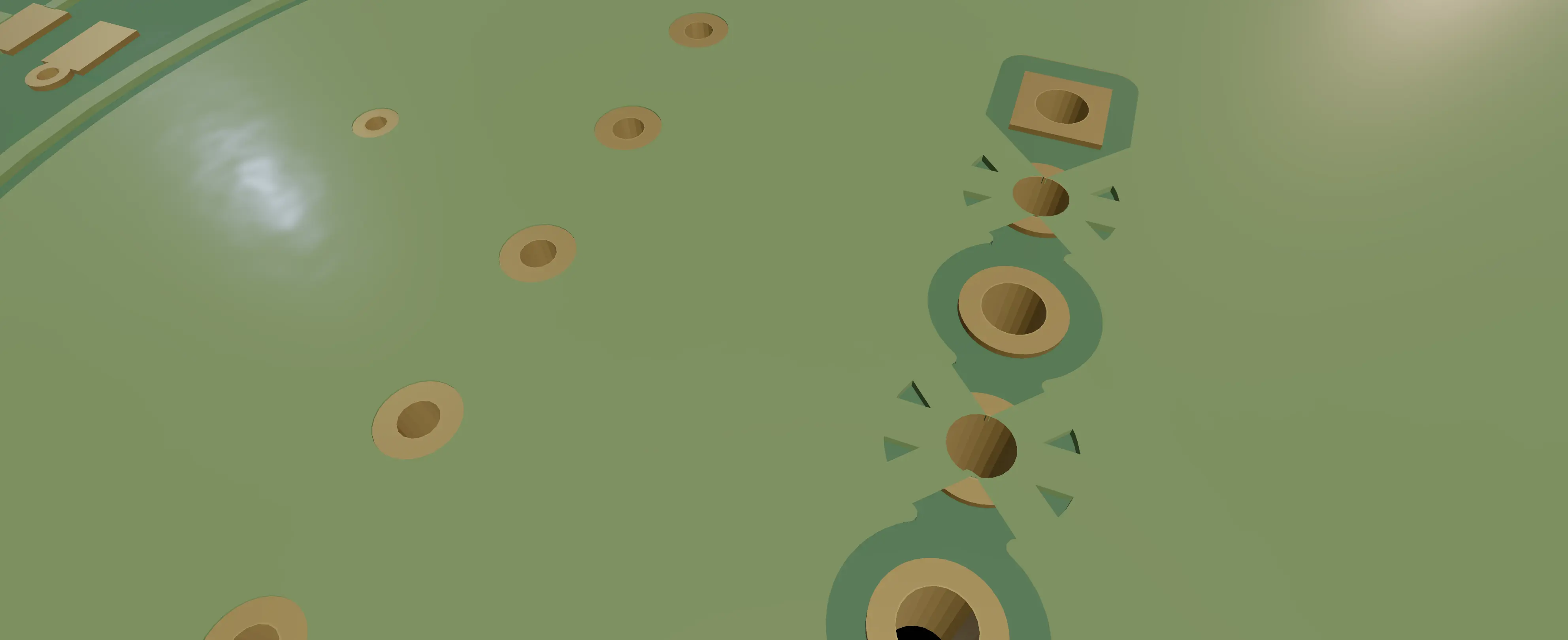
Thermal relief spokes joining a through-hole pad to a ground pour on a gold-lit 3D render.
Thermal reliefs · 0.6 mm spokes, 0.5 mm gap — copper that still lets the joint be hand-soldered.
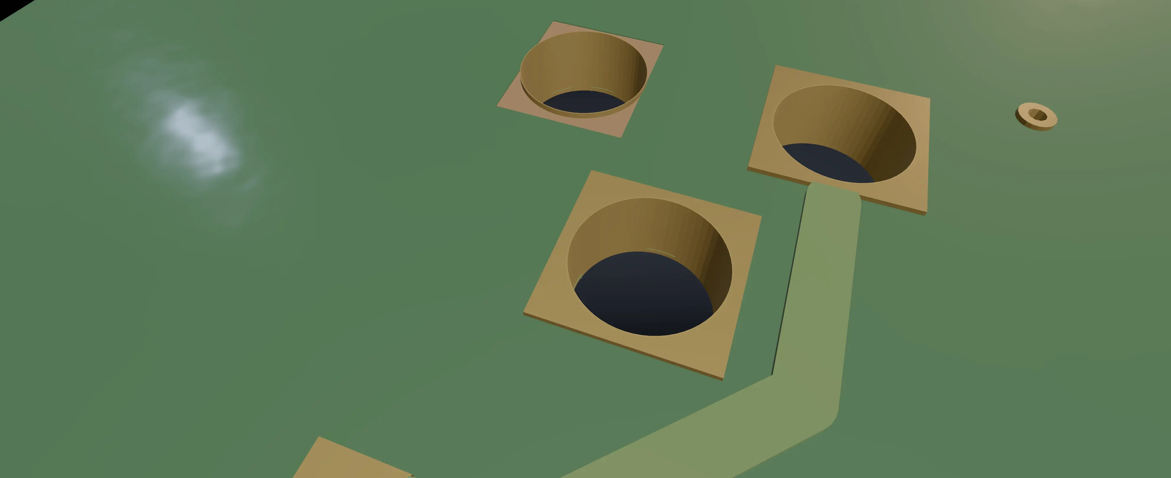
A slotted drill under a barrel jack footprint, rendered on the board as an oblong slot rather than a round hole.
A slotted drill, not a round one — the drill file distinguishes the two, and so does the viewer.

Fine pitch

02

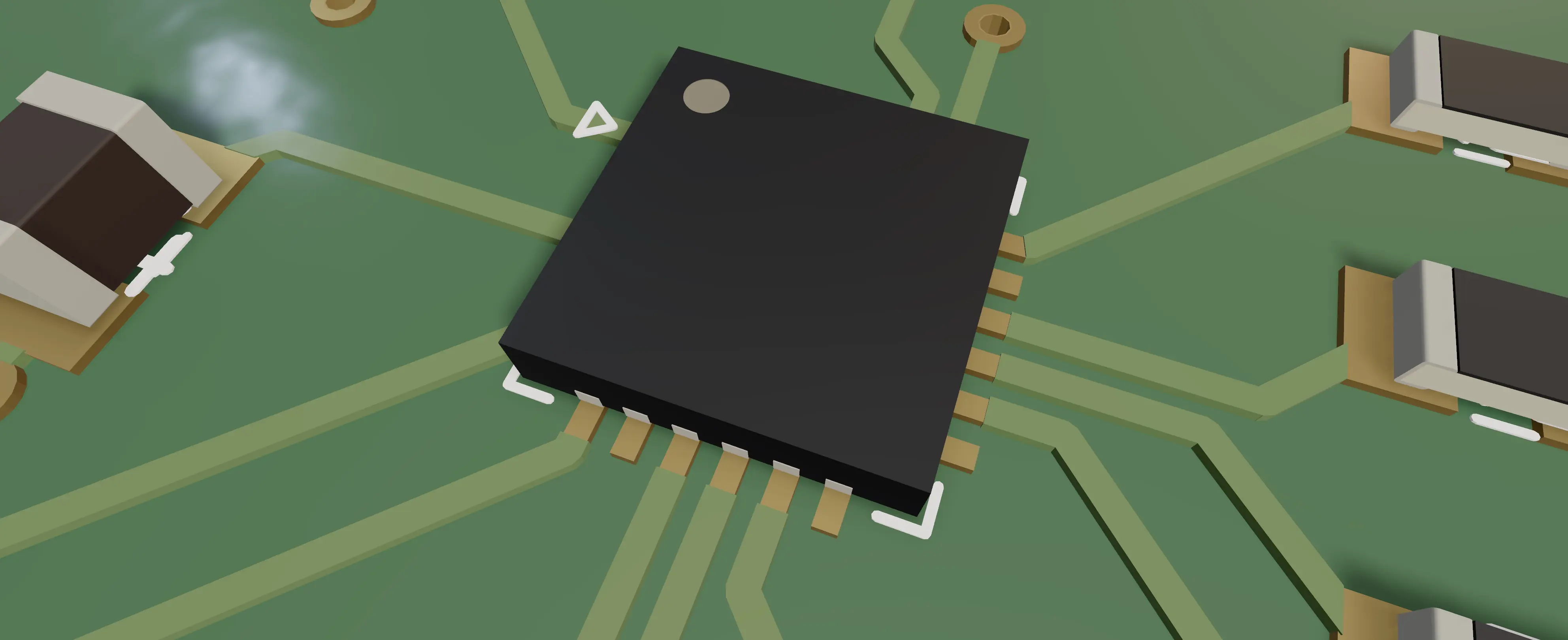
A fine-pitch QFN package on a 3D-rendered board, with one solder-mask opening visible per pad and pin-1 marked with a white triangle.
A 0.5 mm-pitch QFN · one mask opening per pad

A mask opening per pad, at 0.5 mm pitch.

A fine-pitch QFN needs its own solder mask opening per pad rather than one opening for the whole footprint — get that wrong and the paste bridges between pins before the part is even placed. It is drawn correctly here because it is exported correctly, the same story stitching vias through a ground pour tell from the other direction: a drill that has to stay a drill, not fill back in.

0.5 mm pitchone mask opening per pad
Where the pour is routed

What comes out

03

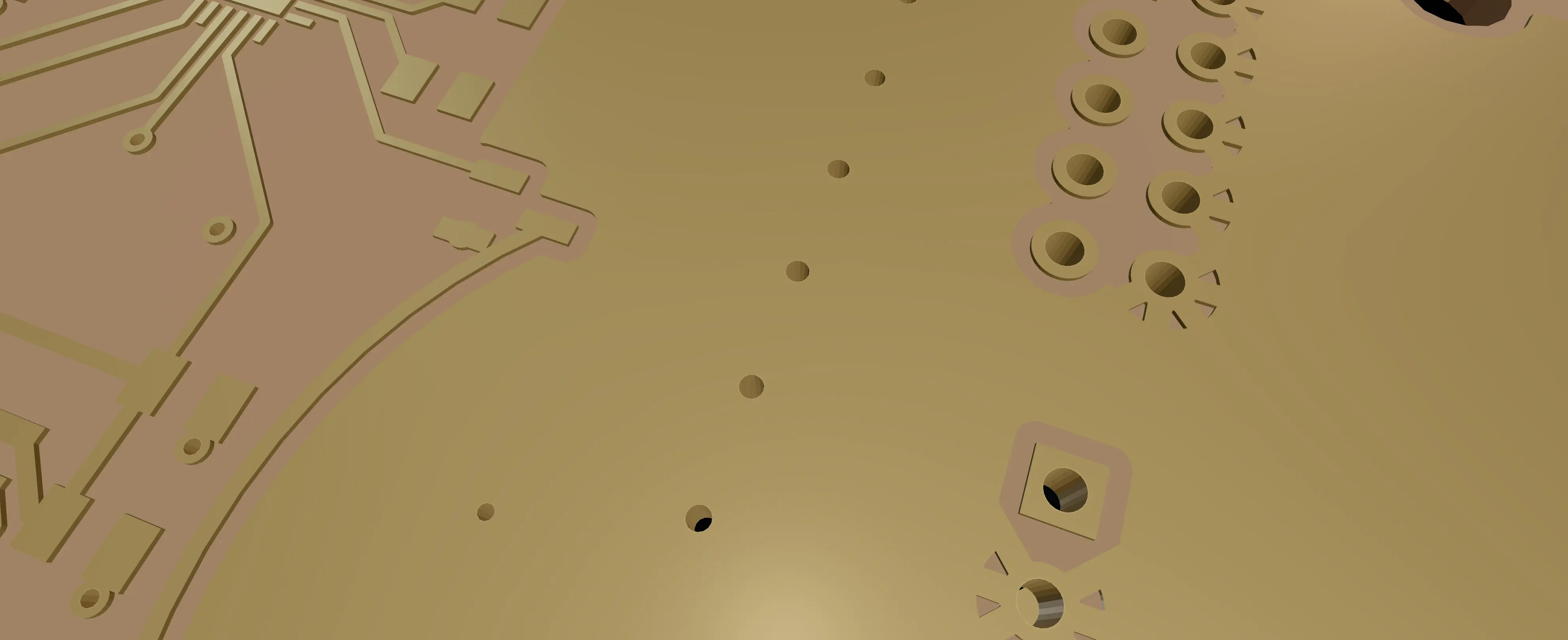
A close 3D render of copper-only pads and thermal-relief spokes on a warm gold-lit background, with plated drill holes down one edge.
Copper on its own · F.Cu — one of the layers a Gerber export carries separately.

Four formats, for four different next steps.

Gerber and drill go to the fab as per-layer artwork, exactly like the copper shown here — one file per layer, nothing merged. STEP and VRML carry the full 3D assembly for the enclosure instead, so the mechanical model is the board rather than a guess at it.

GerberDrillSTEPVRML

Every row, and what it is for.

GerberPer-layer artwork — copper, mask, silkscreen — for the fab to build the board from.
DrillEvery hole, round or slotted, with its own size — separate from the artwork on purpose.
STEPThe full 3D assembly, board and parts, for checking fit against an enclosure in mechanical CAD.
VRMLA textured 3D model of the same assembly, for viewers that read VRML instead of STEP.

Reading and writing runs the other way too: Rivet opens KiCad symbol and footprint libraries and writes symbols and footprints back out in the same format, so a project can move between the two without a conversion step.

Export it. Send it to a fab.

macOS, Windows and Linux · no account. Every platform.